Showing posts with label MPLS. Show all posts

Tuesday, November 17, 2015

ALU 7750 SR L3VPN (VPRN)

MPLS L3 VPN – the Alcatel-Lucent way of implementation


This exercise shows the Alcatel-lucent’s way of implementing MPLS L3 VPN which is named as Virtual Private Routing Network – VPRN. In this technology the PE router keeps separate virtual route-table (VRF) for each customer. VPRN uses two type of MPLS labels: outer label also called transport label, inner label called customer/service label. Customer routes are exchanged between PE using MP-BGP address family VPN-IPv4. PE can run any dynamic or static routing protocol with the CE. Here we used OSPF for PE-CE routing.
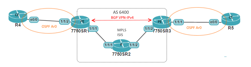
Figure: Network diagram


Router
Interface
IP Address
R1
system
50.50.50.1
ToR2 (port 1/1/1)
192.168.12.1
ToR4 (port 1/1/2) (vrf ABC)
10.10.10.1
R2
system
50.50.50.2
ToR1 (port 1/1/1)
192.168.12.2
ToR3 (port 1/1/2)
192.168.23.2
R3
system
50.50.50.3
ToR2 (port 1/1/2)
192.168.23.3
ToR5 (port 1/1/1) (vrf ABC)
20.20.20.1
R4
E0/0
10.10.10.2
Loopback 1
4.4.4.4
R5
E0/0
20.20.20.2
Loopback 1
5.5.5.5
                                                   
Table: Interface details

Monday, November 16, 2015

ALU 7750 SR Service Architecture

Alcatel-Lucent 7750SR Service model

Various service provider VPN technologies (L2 and L3 VPN) are supported in 7750SR. Alcatel-Lucent's view of implementing these technologies are well structured in a model. Here I will describe the components of this model with sample configuration.

Components


  1. Customer: Every service will be associated with a customer ID, which has no real effect on the router functions. Its mainly used for reporting purpose.
  2. Service: Any VPN service (VPWS, VPLS, VPRN) should have an ID and must be associated with a customer.
  3. SAP: Service access point (SAP) is simply the interfaces facing the customer devices
  4. SDP: Service distribution point (SDP) is the logical interface representing the transport tunnel towards other PEs. It actually establishes a T-LDP.


Configuration Example


##### Creation of a customer #####

*A:PE-1# configure service customer 111 create
*A:PE-1>config>service>cust$ description "Customer ABC"
*A:PE-1>config>service>cust$ phone "+1-222-555-6666"
##### Configuration of SDP #####
*A:PE-1# configure service sdp 2 mpls create
*A:PE-1>config>service>sdp$ far-end 10.10.10.2
*A:PE-1>config>service>sdp$ ldp
#### Creation of an epipe/vpws service ####
*A:PE-1# configure service epipe 55 customer 111 create
*A:PE-1>config>service>epipe$ sap 1/1/2 create
*A:PE-1>config>service>epipe>sap$ exit
*A:PE-1>config>service>epipe# spoke-sdp 2:55 create
*A:PE-1>config>service>epipe>spoke-sdp$ exit
*A:PE-1>config>service>sdp$ no shutdown

Wednesday, July 30, 2014

MPLS L3 VPN - Part 1

MPLS Core setup


·         LDP and IGP in core

P routers

Enable LDP
mpls label protocol ldp
interface Fastethernet x/x             
(x/x = all interface)
              mpls ip

Enable core IGP
router ospf  1
     network 0.0.0.0 255.255.255.255 area 0

PE routers
Enable LDP
mpls label protocol ldp
interface Fastethernet x/x
  (x/x = loopback + all int facing P, not facing CE)
         mpls ip

Enable core IGP
router ospf  1
     network x.x.x.x 0.0.0.255 area 0
(x.x.x.x = interface facing P, not facing CE)


·         VPNv4 between PEs

PE routers

Enable MP-BGP VPNv4
router bgp 100
      no bgp default ipv4-unicast
      neighbor x.x.x.x remote-as 100
      neighbor x.x.x.x update-source loopback1
      address-family vpnv4 unicast
              neighbor x.x.x.x activate
              neighbor x.x.x.x send-community extended


·         VRF Configuration

PE routers

Create VRF
ip vrf AAA  (only for ipv4)
“or”  vrf definition AAA    (for both ipv4+ipv6)

    rd 100:1
    route-target export 100:1
    route-target  import 100:1


Assign interface to VRF
Interface Fa x/x            (interface facing CE)
    ip vrf forwarding AAA
    ip address …