Friday, February 26, 2016

SDN Controller - OpenDayLight

 SDN Controller - OpenDayLight - Build your own test lab

Is it time to throw away traditional switching-routing technologies and embrace SDN ?? I don’t think so yet, but we are certainly moving towards that.
There are a lot of resources out there in the internet regarding Software Defined networking (SDN). Big number of network vendors are releasing SDN products including many industry leaders. There are quite a few opensource SDN Controllers as well: OpenDayLight, OpenContrail, Floodlight, Ryu.
As a network world geek, I can't resist trying out one of these SDN controllers. Below are the simplest steps of installing OpenDaylight(ODL) and Mininet to get started. I used Ubuntu 12 in a virtual machine for this test.


Step 1: Install ODL
Get the download link of ODL you desire
Extract the compressed file.
tar -zxvf distribution-karaf-0.3.3-Lithium-SR3.tar.gz
Install java, maven which are prerequisite for ODL.
sudo apt-get install openjdk-7-jre openjdk-7-jdk maven
Step 2: Start ODL
Export JAVA_HOME path and start Karaf
export JAVA_HOME=/usr/lib/jvm/java-7-openjdk-i386/
cd distribution-karaf-0.3.3-Lithium-SR3/
./bin/karaf
Add L2 switch and Web-gui features from karaf console.
feature:install odl-restconf odl-l2switch-switch odl-openflowplugin-all odl-mdsal-apidocs odl-dlux-all
Step 3: Install and run Mininet
Mininet is a simulation tool to create virtual network supporting openflow.
sudo apt-get install mininet
You might want to run “apt-get update” beforehand to get updated list of packages from the repository.
Run mininet with tree topology
sudo mn --controller=remote,ip=127.0.0.1 --topo=tree,3
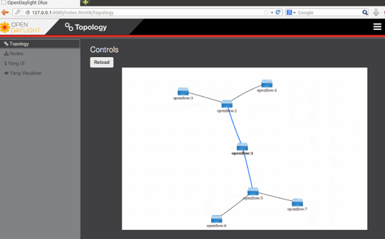
Step 5: Open ODL Web Interface
Enter http://localhost:8080/index.html in your browser with default user and password (admin/admin) to login.

Sunday, January 31, 2016

MTU, fragmentation and reassembly

Recently, I got the opportunity to work in a freshly built LTE/4G core and backhaul network. We observe a strange problem of the network where video traffic (RTSP/UDP) from UE devices in an APN were not reaching the video management servers. Although http or ftp traffic was passing through.
After hours of search, finally the problem was discovered in a one of the EPC component where it had a smaller MTU. Http traffic might have passed due to PMTUD.
Realizing the importance of MTU, let’s review this old school topic of networking.
MTU
The Maximum Transmission Unit (MTU) is the largest number of bytes in a single datagram can have on a particular data communications link.
Usually, in most Ethernet access networks it is 1500 bytes for IP packet.
At Layer 2, standard fame size is 1518 bytes, which includes additional header of 14 bytes and FCS of 4 bytes.
Other communication media types have different MTU size. Example: SONET/SDH has MTU of 4470 bytes.
https://habrastorage.org/getpro/habr/post_images/6c1/6da/135/6c16da13526de3dfd0368d31a5f1b6d9.jpg
Different type of encapsulation adds overhead.
  • GRE (IP Protocol 47) adds 24 bytes (20 byte IPv4 header, 4 byte GRE header)
  • MPLS adds 4 bytes for each label in the stack
  • IEEE 802.1Q tag adds 4 bytes (Q-in-Q would add 8 bytes)
  • VXLAN adds 50 bytes
  • OTV adds 42 bytes
  • IPsec encryption can add 52-76 bytes of overhead depending on transport or tunnel mode and the encryption/authentication algorithm
http://www.cisco.com/c/dam/en/us/td/i/000001-100000/80001-85000/81001-82000/81608.ps/_jcr_content/renditions/81608.jpg

Fragmentation
IP fragmentation involves breaking a datagram into a number of pieces that can be reassembled later.
Routers can fragment IPv4 packets unless the Do-Not-Fragment (DF) bit is set to 1 in the IPv4 header.
Identification, total length, fragment offset, “more fragments" and "don't fragment" flags in the IP header, are used for IP fragmentation and reassembly.
Fragmentation and reassembly of packets increase CPU and memory overhead.
pmtud_ipfrag_02.gif

MSS
Maximum segment size (MSS) is 40 bytes smaller than the MTU.
MSS = MTU – (IP Header + TCP header)
To assist in avoiding fragmentation between endpoints of TCP connection, MSS value is exchanged and lowest is set.
PMTUD
Path MTU Discovery (PMTUD) is used to avoid fragmentation in the path between the endpoints.
It is used to dynamically determine the lowest MTU of routers along the path from a packet's source to its destination.
PMTUD is only supported by TCP.

References

Monday, December 14, 2015

Notes on FabricPath

FabricPath facts

Creator of STP, Radia Perlman, developed TRILL – Transparent Interconnect of Lots of Link to overcome the limitations of STP. Cisco enhanced the protocol and named it FabricPath.

http://www.cisco.com/c/dam/en/us/products/collateral/interfaces-modules/mds-9000-10-gbps-8-port-fcoe-module/white_paper_c11-644818.doc/_jcr_content/renditions/white_paper_c11-644818-2.jpg
Limitation of STP – As the figure above clearly shows that STP allows only a single path to destination in a L2 domain and blocks the redundant path. Whereas Fabricpath enables all path, scalable upto 16 ECMP, which ensures the utilization of full available bandwidth.
Difference with vPC -  vPC addresses the blocked link limitation, but is only scalable to two spine or core switch and still relies on STP for loop prevention. vPC+, an enhanced version of vPC can be used in conjunction with fabricpath.
A single switch – A cloud of fabricpath capable switches can also be connected to a traditional STP network, where the cloud is considered as one single switch. Ideally, the fabricpath cloud is configured as root bridge in the STP domain.
C:\Users\Dell01\Desktop\fabricpath.png

Link state protocol – Layer 3 routing intelligence brought to Layer 2. FabricPath uses ISIS routing protocol with FabricPath-specific extensions, like exchanging switch ID (SID) to determine reachability and path selection in the FabricPath domain.
Conversational learning of mac address – In a classical switched network all switches maintains table all MAC address of hosts in the network. This table, TCAM can grow larger as hosts increases. Fabricpath switch learns remote MAC addresses only if the remote device is having a bidirectional conversation with a locally connected device.

Saturday, November 28, 2015

VXLAN simplified - what, why and how ?

What is VXLAN?

  • VXLAN - Virtual eXtensible Local Area Network, is an encapsulation or tunneling method to carry the L2 overlay network traffic on top of L3 networks.
  • VXLAN encapsulates original L2 frames in to a UDP packet (Port 4789).
  • It is developed by VMware, Cisco, Arista and Broadcom.


Why use VXLAN?


Let’s imagine a datacenter network scenario where there is a requirement for a customer or system to have the virtual machines in a single subnet or broadcast domain. The virtual machines are located in different hosts which are separated by racks, datacenters or even geographically and are in separate L3 segments of the network. How do we fulfill the requirement? VXLAN to the rescue.

By virtualizing Layer 2 VXLAN can bridge datacenters without changing address or gateway. A smart guy might ask: “We can do that with OTV, then why VXLAN?” Well, it’s true that they can serve the same purpose, but the difference is the limitation of number of LAN segments which is 4094 (maximum VLANs) in case of OTV. The VXLAN header provides a 24-bit address space called the VNI (VXLAN Network Identifier) to separate out tenant segments, which is 16 million.

How does VXLAN work?


Two major terminology of VXLAN are VTEP and VNI.

VTEP -  VXLAN Tunnel End Point, as the name implies it’s the point where VM traffic is encapsulated or de-encapsulated. This function is performed in the hypervisor or switch.

VNI - Virtual Network Identifier, which is used to identify VXLAN segments. All the hosts configured in a VNI are considered to be in the same broadcast domain and synchronized (Ex. MAC and ARP table).
VXLAN control plane can operate in three modes for traffic replication: Multicast, Unicast and Hybrid

Multicast Mode
  • Multicast mode relies on the capability multicast protocols (IGMP, PIM) of the physical network devices.
  • In this mode a multicast address is associated with each VXLAN segment or VID. Each host hosting the VM related to that segment joints the multicast group.
  • Broadcast, Unknown unicast and Multicast traffic known in short as BUM from the VMs are transmitted using multicast capability of the physical network devices.

Figure: Multicast mode

Unicast Mode
  • In unicast mode a Proxy VTEP referred as UTEP, is elected in each physical network segment to replicated multi destination traffic or BUM.
  • This mode does not need any special configuration or features in the physical network devices.
Figure: Unicast mode

Hybrid Mode
  • Hybrid mode is very similar to the unicast mode, other than multicast capability used only in the physical L2 switches. Multicast routing (PIM) is not required.
  • Multicast is used to replicate BUM traffic in the same physical L2 domain. Unicast is used to replicate BUM traffic between different physical network subnet.
Figure: Hybrid mode


Reference:

Thursday, November 26, 2015

Inter-AS VPWS in Alcatel-Lucent SR


Figure: Network diagram

In this post we will discuss on implementing L2 VPN service in Alcatel-Lucent. The two types of L2 VPN supported in ALU service router are VPWS or VLL and VPS. Different type of VPWS service exists based on network type: epipe, fpipe, apipe, ipipe. In our exercise we will configure epipe (e=ethernet) service.  

The configuration of epipe service is pretty simple in 7750SR. Refer here for service model.
To add a bit complexity, we will try it in an Inter-AS network environment.

The implementation approach in our example here is referred as Model-C. In this model BGP is used for signaling service label and LDP for transport label.

Tuesday, November 17, 2015

ALU 7750 SR L3VPN (VPRN)

MPLS L3 VPN – the Alcatel-Lucent way of implementation


This exercise shows the Alcatel-lucent’s way of implementing MPLS L3 VPN which is named as Virtual Private Routing Network – VPRN. In this technology the PE router keeps separate virtual route-table (VRF) for each customer. VPRN uses two type of MPLS labels: outer label also called transport label, inner label called customer/service label. Customer routes are exchanged between PE using MP-BGP address family VPN-IPv4. PE can run any dynamic or static routing protocol with the CE. Here we used OSPF for PE-CE routing.
Figure: Network diagram


Router
Interface
IP Address
R1
system
50.50.50.1
ToR2 (port 1/1/1)
192.168.12.1
ToR4 (port 1/1/2) (vrf ABC)
10.10.10.1
R2
system
50.50.50.2
ToR1 (port 1/1/1)
192.168.12.2
ToR3 (port 1/1/2)
192.168.23.2
R3
system
50.50.50.3
ToR2 (port 1/1/2)
192.168.23.3
ToR5 (port 1/1/1) (vrf ABC)
20.20.20.1
R4
E0/0
10.10.10.2
Loopback 1
4.4.4.4
R5
E0/0
20.20.20.2
Loopback 1
5.5.5.5
                                                   
Table: Interface details

Monday, November 16, 2015

ALU 7750 SR Service Architecture

Alcatel-Lucent 7750SR Service model

Various service provider VPN technologies (L2 and L3 VPN) are supported in 7750SR. Alcatel-Lucent's view of implementing these technologies are well structured in a model. Here I will describe the components of this model with sample configuration.

Components


  1. Customer: Every service will be associated with a customer ID, which has no real effect on the router functions. Its mainly used for reporting purpose.
  2. Service: Any VPN service (VPWS, VPLS, VPRN) should have an ID and must be associated with a customer.
  3. SAP: Service access point (SAP) is simply the interfaces facing the customer devices
  4. SDP: Service distribution point (SDP) is the logical interface representing the transport tunnel towards other PEs. It actually establishes a T-LDP.


Configuration Example


##### Creation of a customer #####

*A:PE-1# configure service customer 111 create
*A:PE-1>config>service>cust$ description "Customer ABC"
*A:PE-1>config>service>cust$ phone "+1-222-555-6666"
##### Configuration of SDP #####
*A:PE-1# configure service sdp 2 mpls create
*A:PE-1>config>service>sdp$ far-end 10.10.10.2
*A:PE-1>config>service>sdp$ ldp
#### Creation of an epipe/vpws service ####
*A:PE-1# configure service epipe 55 customer 111 create
*A:PE-1>config>service>epipe$ sap 1/1/2 create
*A:PE-1>config>service>epipe>sap$ exit
*A:PE-1>config>service>epipe# spoke-sdp 2:55 create
*A:PE-1>config>service>epipe>spoke-sdp$ exit
*A:PE-1>config>service>sdp$ no shutdown