MPLS L3 VPN – the Alcatel-Lucent way of implementation
This exercise shows the Alcatel-lucent’s way of implementing MPLS L3 VPN which is named as Virtual Private Routing Network – VPRN. In this technology the PE router keeps separate virtual route-table (VRF) for each customer. VPRN uses two type of MPLS labels: outer label also called transport label, inner label called customer/service label. Customer routes are exchanged between PE using MP-BGP address family VPN-IPv4. PE can run any dynamic or static routing protocol with the CE. Here we used OSPF for PE-CE routing.
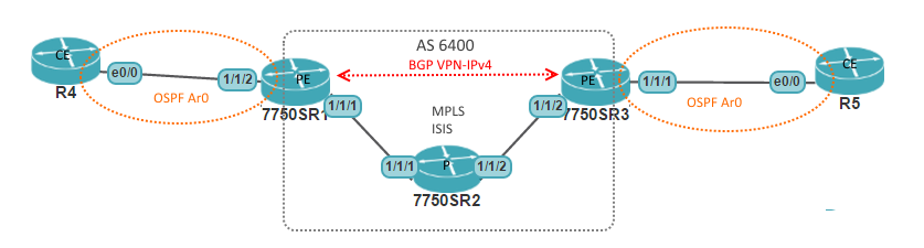
Figure: Network diagram
Router
|
Interface
|
IP Address
|
R1
|
system
|
50.50.50.1
|
ToR2 (port 1/1/1)
|
192.168.12.1
| |
ToR4 (port 1/1/2) (vrf ABC)
|
10.10.10.1
| |
R2
|
system
|
50.50.50.2
|
ToR1 (port 1/1/1)
|
192.168.12.2
| |
ToR3 (port 1/1/2)
|
192.168.23.2
| |
R3
|
system
|
50.50.50.3
|
ToR2 (port 1/1/2)
|
192.168.23.3
| |
ToR5 (port 1/1/1) (vrf ABC)
|
20.20.20.1
| |
R4
|
E0/0
|
10.10.10.2
|
Loopback 1
|
4.4.4.4
| |
R5
|
E0/0
|
20.20.20.2
|
Loopback 1
|
5.5.5.5
|
Table: Interface details
Step 1: IGP and MPLS
First we have to prepare the MPLS and IGP of the service provider core. In this exercise we will use ISIS as IGP and LDP for MPLS label distribution.
ISIS Configuration
R1
|
R2
|
R3
|
configure router isis
level-capability level-2
area-id 49.0000
level 2
wide-metrics-only
exit
interface "system"
interface "ToR2"
no shutdown
|
configure router isis
level-capability level-2
area-id 49.0000
level 2
wide-metrics-only
exit
interface "system"
interface "ToR1"
interface "ToR3"
no shutdown
|
configure router isis
level-capability level-2
area-id 49.0000
level 2
wide-metrics-only
exit
interface "system"
interface "ToR2"
no shutdown
|
ISIS Verification
A:R2# show router isis adjacency
===============================================================================
Router Base ISIS Instance 0 Adjacency
===============================================================================
System ID Usage State Hold Interface MT-ID
-------------------------------------------------------------------------------
R1 L2 Up 23 ToR1 0
R3 L2 Up 7 ToR3 0
-------------------------------------------------------------------------------
Adjacencies : 2
===============================================================================
|
LDP Configuration
R1
|
R2
|
R3
|
configure router ldp
interface-parameters
interface "ToR2"
exit
|
configure router ldp
interface-parameters
interface "ToR1"
interface "ToR3"
exit
|
configure router ldp
interface-parameters
interface "ToR2"
exit
|
*By default LDP will only create labels for system address. For other prefixes a policy statement has to be defined and exported in LDP
LDP Verification
A:R2# show router ldp peer
===============================================================================
LDP Peers
===============================================================================
Peer Adm Opr Hello Hold KA KA Passive Auto
Factor Time Factor Timeout Mode Created
-------------------------------------------------------------------------------
50.50.50.1 Up Up 3 45 4 40 Disabled Yes
50.50.50.3 Up Up 3 45 4 40 Disabled Yes
-------------------------------------------------------------------------------
No. of Peers: 2
===============================================================================
|
Step 2: MP-BGP
MP-BGP peering needs to be configured between the PE routers to exchange customer routes. BGP address family has to be declared as vpn-ipv4.
R1
|
R3
|
configure router autonomous-system 65000
configure router bgp
group "SP1"
family vpn-ipv4
peer-as 65000
neighbor 50.50.50.3
next-hop-self
exit
exit
no shutdown
|
configure router autonomous-system 65000
configure router bgp
group "SP1"
family vpn-ipv4
peer-as 65000
neighbor 50.50.50.1
next-hop-self
exit
exit
no shutdown
|
MP-BGP verification
A:R3# show router bgp summary
….output omitted….
===============================================================================
BGP Summary
===============================================================================
Neighbor
AS PktRcvd InQ Up/Down State|Rcv/Act/Sent (Addr Family)
PktSent OutQ
-------------------------------------------------------------------------------
50.50.50.1
65000 39 0 00h01m34s Active
10 0
-------------------------------------------------------------------------------
|
Step 3: VPRN Service
VPRN service configuration steps basically involve:
- Creation of customer
- Creation of vprn service
- Add route-distinguisher
- Add interface and assign sap, ip address
- Add route-target bgp community
Refer to ALU Service model concept here.
Route distinguisher is the additional string (64bit) added to the IP prefixes which makes them unique and used to separate customer routes. Refer to RFC 4364.
On the other hand, Route-target is a BGP extended community used to share the routes over MP-BGP by export and import. Refer to RFC 4360.
Route distinguisher is the additional string (64bit) added to the IP prefixes which makes them unique and used to separate customer routes. Refer to RFC 4364.
On the other hand, Route-target is a BGP extended community used to share the routes over MP-BGP by export and import. Refer to RFC 4360.
Service VPRN configuration
R1
|
R3
|
configure service customer 100 create
configure service vprn 20 customer 100 create
route-distinguisher 65000:100
auto-bind ldp
vrf-target target:65000:20
interface "ABC" create
address 10.10.10.1/24
sap 1/1/2 create
exit
exit
|
configure service customer 100 create
configure service vprn 20 customer 100 create
route-distinguisher 65000:100
auto-bind ldp
vrf-target target:65000:20
interface "ABC" create
address 20.20.20.1/24
sap 1/1/1 create
exit
exit
|
Service VPRN verification
A:R3# show service id 20 base
===============================================================================
Service Basic Information
===============================================================================
Service Id : 20 Vpn Id : 0
Service Type : VPRN
Name : (Not Specified)
Description : (Not Specified)
Customer Id : 100 Creation Origin : manual
Last Status Change: 11/16/2015 10:00:16
Last Mgmt Change : 11/16/2015 10:00:16
Admin State : Up Oper State : Up
Route Dist. : 65000:100 VPRN Type : regular
AS Number : None Router Id : 50.50.50.3
ECMP : Enabled ECMP Max Routes : 1
Max IPv4 Routes : No Limit Auto Bind : LDP
Max IPv6 Routes : No Limit
Ignore NH Metric : Disabled
Hash Label : Disabled
Vrf Target : target:65000:20
Vrf Import : None
Vrf Export : None
MVPN Vrf Target : None
MVPN Vrf Import : None
MVPN Vrf Export : None
Car. Sup C-VPN : Disabled
Label mode : vrf
BGP VPN Backup : Disabled
BGP Export Inacti*: Disabled
SAP Count : 1 SDP Bind Count : 0
-------------------------------------------------------------------------------
Service Access & Destination Points
-------------------------------------------------------------------------------
Identifier Type AdmMTU OprMTU Adm Opr
-------------------------------------------------------------------------------
sap:1/1/1 null 1514 1514 Up Up
===============================================================================
* indicates that the corresponding row element may have been truncated.
|
Step 4: PE-CE routing
OSPF have to be configure under service vprn 20 branch in the PE routers, NOT user global routing.
OSPF basic configuration
PE routers (R1 and R3)
|
CE routers (R4 and R5)
|
configure service vprn 20
ospf
area 0.0.0.0
interface "ABC"
no shutdown
exit
exit
exit
|
router ospf 1
network 0.0.0.0 255.255.255.255 area 0
|
VPN-IPv4 routes received from the MP-BGP in PE routers has to be exported in the OSPF using policy
OSPF export configuration
PE routers (R1 and R3)
|
configure router policy-options
begin
policy-statement "abcRT"
entry 10
from
protocol bgp-vpn
exit
action accept
exit
exit
exit
commit
exit
configure service vprn 20 ospf export "abcRT"
|
PE-CE OSPF Verification
A:R3# show router 20 ospf neighbor
===============================================================================
OSPFv2 (0) all neighbors
===============================================================================
Interface-Name Rtr Id State Pri RetxQ TTL
Area-Id
-------------------------------------------------------------------------------
ABC 5.5.5.5 Full 1 0 39
0.0.0.0
-------------------------------------------------------------------------------
No. of Neighbors: 1
===============================================================================
R5# sh ip route ospf
…output omitted…
Gateway of last resort is not set
4.0.0.0/32 is subnetted, 1 subnets
O E2 4.4.4.4 [110/101] via 20.20.20.1, 00:09:39, Ethernet0/0
10.0.0.0/24 is subnetted, 1 subnets
O E2 10.10.10.0 [110/1] via 20.20.20.1, 00:09:39, Ethernet0/0
|
*The exercise is done in a virtual environment using Unetlab. Output may vary in real devices. Ask me if you need the lab files.
Great lab. How to get alcatel 7750 virtual lab?
ReplyDeleteRespect and I have a neat proposal: Who To Contact For House Renovation best house renovations
ReplyDelete