Monday, December 14, 2015

Notes on FabricPath

FabricPath facts

Creator of STP, Radia Perlman, developed TRILL – Transparent Interconnect of Lots of Link to overcome the limitations of STP. Cisco enhanced the protocol and named it FabricPath.

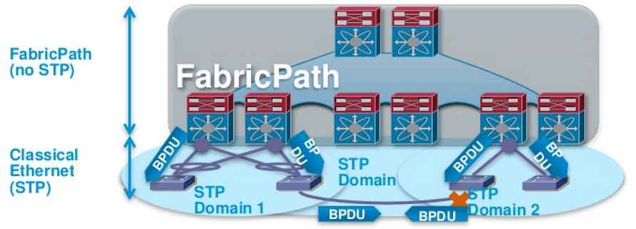
http://www.cisco.com/c/dam/en/us/products/collateral/interfaces-modules/mds-9000-10-gbps-8-port-fcoe-module/white_paper_c11-644818.doc/_jcr_content/renditions/white_paper_c11-644818-2.jpg
Limitation of STP – As the figure above clearly shows that STP allows only a single path to destination in a L2 domain and blocks the redundant path. Whereas Fabricpath enables all path, scalable upto 16 ECMP, which ensures the utilization of full available bandwidth.
Difference with vPC -  vPC addresses the blocked link limitation, but is only scalable to two spine or core switch and still relies on STP for loop prevention. vPC+, an enhanced version of vPC can be used in conjunction with fabricpath.
A single switch – A cloud of fabricpath capable switches can also be connected to a traditional STP network, where the cloud is considered as one single switch. Ideally, the fabricpath cloud is configured as root bridge in the STP domain.
C:\Users\Dell01\Desktop\fabricpath.png

Link state protocol – Layer 3 routing intelligence brought to Layer 2. FabricPath uses ISIS routing protocol with FabricPath-specific extensions, like exchanging switch ID (SID) to determine reachability and path selection in the FabricPath domain.
Conversational learning of mac address – In a classical switched network all switches maintains table all MAC address of hosts in the network. This table, TCAM can grow larger as hosts increases. Fabricpath switch learns remote MAC addresses only if the remote device is having a bidirectional conversation with a locally connected device.

Saturday, November 28, 2015

VXLAN simplified - what, why and how ?

What is VXLAN?

  • VXLAN - Virtual eXtensible Local Area Network, is an encapsulation or tunneling method to carry the L2 overlay network traffic on top of L3 networks.
  • VXLAN encapsulates original L2 frames in to a UDP packet (Port 4789).
  • It is developed by VMware, Cisco, Arista and Broadcom.


Why use VXLAN?


Let’s imagine a datacenter network scenario where there is a requirement for a customer or system to have the virtual machines in a single subnet or broadcast domain. The virtual machines are located in different hosts which are separated by racks, datacenters or even geographically and are in separate L3 segments of the network. How do we fulfill the requirement? VXLAN to the rescue.

By virtualizing Layer 2 VXLAN can bridge datacenters without changing address or gateway. A smart guy might ask: “We can do that with OTV, then why VXLAN?” Well, it’s true that they can serve the same purpose, but the difference is the limitation of number of LAN segments which is 4094 (maximum VLANs) in case of OTV. The VXLAN header provides a 24-bit address space called the VNI (VXLAN Network Identifier) to separate out tenant segments, which is 16 million.

How does VXLAN work?


Two major terminology of VXLAN are VTEP and VNI.

VTEP -  VXLAN Tunnel End Point, as the name implies it’s the point where VM traffic is encapsulated or de-encapsulated. This function is performed in the hypervisor or switch.

VNI - Virtual Network Identifier, which is used to identify VXLAN segments. All the hosts configured in a VNI are considered to be in the same broadcast domain and synchronized (Ex. MAC and ARP table).
VXLAN control plane can operate in three modes for traffic replication: Multicast, Unicast and Hybrid

Multicast Mode
  • Multicast mode relies on the capability multicast protocols (IGMP, PIM) of the physical network devices.
  • In this mode a multicast address is associated with each VXLAN segment or VID. Each host hosting the VM related to that segment joints the multicast group.
  • Broadcast, Unknown unicast and Multicast traffic known in short as BUM from the VMs are transmitted using multicast capability of the physical network devices.

Figure: Multicast mode

Unicast Mode
  • In unicast mode a Proxy VTEP referred as UTEP, is elected in each physical network segment to replicated multi destination traffic or BUM.
  • This mode does not need any special configuration or features in the physical network devices.
Figure: Unicast mode

Hybrid Mode
  • Hybrid mode is very similar to the unicast mode, other than multicast capability used only in the physical L2 switches. Multicast routing (PIM) is not required.
  • Multicast is used to replicate BUM traffic in the same physical L2 domain. Unicast is used to replicate BUM traffic between different physical network subnet.
Figure: Hybrid mode


Reference:

Thursday, November 26, 2015

Inter-AS VPWS in Alcatel-Lucent SR


Figure: Network diagram

In this post we will discuss on implementing L2 VPN service in Alcatel-Lucent. The two types of L2 VPN supported in ALU service router are VPWS or VLL and VPS. Different type of VPWS service exists based on network type: epipe, fpipe, apipe, ipipe. In our exercise we will configure epipe (e=ethernet) service.  

The configuration of epipe service is pretty simple in 7750SR. Refer here for service model.
To add a bit complexity, we will try it in an Inter-AS network environment.

The implementation approach in our example here is referred as Model-C. In this model BGP is used for signaling service label and LDP for transport label.

Tuesday, November 17, 2015

ALU 7750 SR L3VPN (VPRN)

MPLS L3 VPN – the Alcatel-Lucent way of implementation


This exercise shows the Alcatel-lucent’s way of implementing MPLS L3 VPN which is named as Virtual Private Routing Network – VPRN. In this technology the PE router keeps separate virtual route-table (VRF) for each customer. VPRN uses two type of MPLS labels: outer label also called transport label, inner label called customer/service label. Customer routes are exchanged between PE using MP-BGP address family VPN-IPv4. PE can run any dynamic or static routing protocol with the CE. Here we used OSPF for PE-CE routing.
Figure: Network diagram


Router
Interface
IP Address
R1
system
50.50.50.1
ToR2 (port 1/1/1)
192.168.12.1
ToR4 (port 1/1/2) (vrf ABC)
10.10.10.1
R2
system
50.50.50.2
ToR1 (port 1/1/1)
192.168.12.2
ToR3 (port 1/1/2)
192.168.23.2
R3
system
50.50.50.3
ToR2 (port 1/1/2)
192.168.23.3
ToR5 (port 1/1/1) (vrf ABC)
20.20.20.1
R4
E0/0
10.10.10.2
Loopback 1
4.4.4.4
R5
E0/0
20.20.20.2
Loopback 1
5.5.5.5
                                                   
Table: Interface details

Monday, November 16, 2015

ALU 7750 SR Service Architecture

Alcatel-Lucent 7750SR Service model

Various service provider VPN technologies (L2 and L3 VPN) are supported in 7750SR. Alcatel-Lucent's view of implementing these technologies are well structured in a model. Here I will describe the components of this model with sample configuration.

Components


  1. Customer: Every service will be associated with a customer ID, which has no real effect on the router functions. Its mainly used for reporting purpose.
  2. Service: Any VPN service (VPWS, VPLS, VPRN) should have an ID and must be associated with a customer.
  3. SAP: Service access point (SAP) is simply the interfaces facing the customer devices
  4. SDP: Service distribution point (SDP) is the logical interface representing the transport tunnel towards other PEs. It actually establishes a T-LDP.


Configuration Example


##### Creation of a customer #####

*A:PE-1# configure service customer 111 create
*A:PE-1>config>service>cust$ description "Customer ABC"
*A:PE-1>config>service>cust$ phone "+1-222-555-6666"
##### Configuration of SDP #####
*A:PE-1# configure service sdp 2 mpls create
*A:PE-1>config>service>sdp$ far-end 10.10.10.2
*A:PE-1>config>service>sdp$ ldp
#### Creation of an epipe/vpws service ####
*A:PE-1# configure service epipe 55 customer 111 create
*A:PE-1>config>service>epipe$ sap 1/1/2 create
*A:PE-1>config>service>epipe>sap$ exit
*A:PE-1>config>service>epipe# spoke-sdp 2:55 create
*A:PE-1>config>service>epipe>spoke-sdp$ exit
*A:PE-1>config>service>sdp$ no shutdown

Saturday, October 31, 2015

Alcatel-Lucent 7750SR for Cisco guys

Alcatel-Lucent 7750SR is a wonderful router especially for the Service provider network.  I find the CLI of this router to be very well structured and more logical than Cisco.


Hardware

On the 7750 SR, packet forwarding is handled by the IOM (Input/Output Module) and MDA (Media Dependent Adapter) cards.


The software/firmware (TiMOS) and startup-config of ALU SR router is stored in CF3 (memory card slot) by default.
The hardware modules have to be provisioned first to function:
SR1# configure card 1
SR1>config>card# card-type iom3-xp-b
SR1>config>card# no shutdown
SR1>config>card# mda 1
SR1>config>card>mda# mda-type m5-1gb-sfp-b
SR1>config>card>mda# no shutdown
SR1# configure port 1/1/1
SR1>config>port# no shutdown


View the status of card and ports:
SR1# show card
SR1# show port

Command Help
To view available commands in a branch type: tree

To view current config in a branch type: info
The commands can be executed in a single line also. Example: configure port 1/1/1 no shutdown
A ‘*’ sysmbol is show at the beginning of cli prompt to indicate changes not saved.
To save type: admin save
To view the running config: admin display-config


Layer 3 Addressing
The default interface "system" cannot be deleted and is used as default router-id in ospf/bgp.
*B:PE1# configure router
*B:PE1>config>router# interface system
*B:PE1>config>router>if# address 140.10.0.1/32


IP addresses cannot be assigned directly to port. Logical named interface has to be created first and then it has to be linked with a physical port.
*B:PE1>config>router# interface toCE1
*B:PE1>config>router>if$ address 140.10.0.101/30
*B:PE1>config>router>if$ port 1/1/1


Loopback interface is to be configured as below:
*B:PE1>config>router# interface loopbackTest
*B:PE1>config>router>if$ address 140.10.0.11/32
*B:PE1>config>router>if$ loopback
To view all L3 or routed interfaces:
*B:PE1>config>router# show router interface


Basic Routing For adding a static route:

*B:PE1# configure router
*B:PE1>config>router# static-route 10.10.0.0/16 next-hop 140.10.0.97
To view route table: *B:PE1# show router route-table


OSPF

OSPF configuration is very similar to that of Cisco IOS-XR.
*B:PE1# configure router ospf
*B:PE1>config>router>ospf# area 0
*B:PE1>config>router>ospf>area$ interface system
*B:PE1>config>router>ospf>area>if$ exit
*B:PE1>config>router>ospf>area# interface toPE2
*B:PE1>config>router>ospf>area>if# interface-type point-to-point

To advertise external routes (LSA-5) the ASBR router must have the additional config line:

*B:PE1>config>router>ospf# asbr

It is impossible to distribute external routes without a policy.
*B:PE1# configure router policy-options
>policy-options# begin >policy-options# policy-statement DistributeRT >policy-options>policy-statement$ entry 10 >policy-options>policy-statement>entry$ from protocol direct >policy-options>policy-statement>entry# action accept >policy-options>policy-statement>entry>action# exit
*B:PE1# configure router ospf
*B:PE1>config>router>ospf# export DistributeRT

Some 'show' commands for verifying OSPF:
*B:PE1>config>router>ospf# show router ospf neighbor *B:PE1>config>router>ospf# show router ospf database

BGP

Staring with AS number declartion, follows the bgp configuration. Neighbors are configured inside groups. E-BGP routes cannot be advertised without a policy.

*B:PE1>config>router# autonomous-system 65001
*B:PE1>config>router# bgp
*B:PE1>config>router>bgp# export DistributeRT
*B:PE1>config>router>bgp$ group eBGP
*B:PE1>config>router>bgp>group$ neighbor 140.10.0.98
*B:PE1>config>router>bgp>group>neighbor$ peer-as 65002
*B:PE1>config>router>bgp>group>neighbor$ exit
*B:PE1>config>router>bgp# group iBGP
*B:PE1>config>router>bgp>group$ next-hop-self
*B:PE1>config>router>bgp>group$ neighbor 140.10.0.3
*B:PE1>config>router>bgp>group>neighbor$ peer-as 65001

Some 'show' commands for bgp:
*B:PE1# show router bgp summary *B:PE1# show router bgp neighbor 140.10.0.98 advertised-routes